Create an ESP32 BLE peripheral for iOS #1

This post is part one of a series targeted at helping mobile app developers build their own BLE Peripherals using inexpensive ESP32 hardware in less than 100 lines of code. This can help to more fully understand the BLE protocol. If you’re an iOS developer who would like to build their own BLE Peripherals for learning and exploring the full set of BLE features—or need to build a development simulator for a future device—this is the tutorial for you.
Introduction
This tutorial post is part one of a two-part series developing a Bluetooth BLE Peripheral to use for testing with iOS and Android applications.
- Part one (this part) covers creating a BLE peripheral using an Espressif ESP32 dev kit board using the Arduino IDE.
- Part two covers creating a SwiftUI iOS app that uses Core Bluetooth to connect and communicate with the ESP32 peripheral.
In this first part, I’ll walk through all the steps needed to code and deploy the BLE Peripheral, which includes the following:
- Acquire an ESP32 development board to serve as the peripheral hardware
- Install the Arduino IDE
- Add ESP32 hardware and library support to Arduino
- Write the code that implements the BLE peripheral
- Flash the peripheral code onto the ESP32 hardware
The Use Case
The application you’ll develop in the second and/or third part of this tutorial will be a simple calculator application that provides an iOS app that uses the ESP32 module that is the “brains” of the calculator.
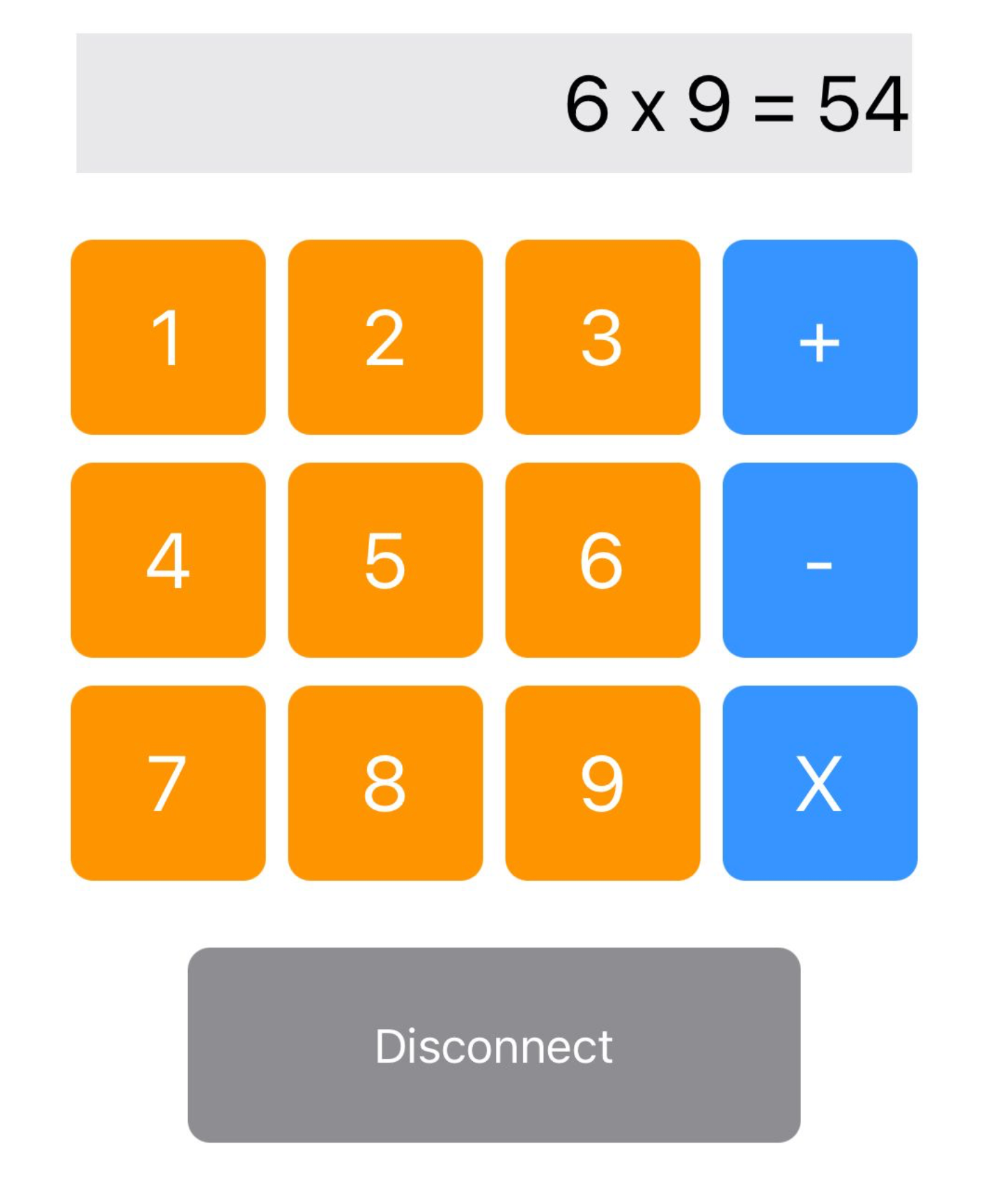
BLE Calculator UI
Of course, in the real-world the phone device could do it’s own calculations! But this app will allow you to develop some fundamental BLE firmware skills and learn to use important BLE features both on the iOS and firmware (ESP32) development environments.
These are the features we’re most interested in learning in this part of the tutorial:
- Creating a BLE peripheral using the ESP32 module
- Creating BLE services, and advertising them so remote clients will discover them
- Creating a write characteristic, which allows remote clients to send data to the BLE peripheral
- Creating a read characteristic, which allows the BLE peripheral to expose data to the remote client
- Using characteristic notifications, allowing the remote client to subscribe to data changes (instead of polling the peripheral)
What’s ESP32?
ESP32 chips are designed by Espressif Systems, and are one of the most common CPUs used in IoT and device control applications. ESP32 modules incorporate WiFi and Bluetooth connectivity as a core feature, which makes them particularly useful as a mobile app development tool.
ESP32 modules are used in production delivered IoT devices, HomeKit devices, and in other BLE and WiFi connected device applications. If you have a requirement to implement BLE integration from an iOS or Android app, there’s a high likelihood that the SoC used in the remote peripheral will be based on ESP32.
The ubiquity in production makes ESP32 a great module to use for learning BLE and creating development simulators for other devices. Another good reason to use ESP32 is their cost. ESP32 Development Modules are readily available from many manufacturers, and they’re relatively inexpensive. Typically a ESP32 DevKit boards can be purchased for around $8-10 (US) each, and have BLE, WiFi and CPU built in at that price point.
The board I’ll use in this tutorial is a Teyleten Robot ESP-WROOM-32 development board which I acquired from Amazon at the low end of this price range. I highly recommend it:
Teyleten Robot ESP-WROOM-32 on Amazon.com
Download Arduino IDE
With an ESP32 dev board in hand, the next step is to download and install the Arduino IDE.
It’s certainly possible to work through this tutorial and learn the process and syntax for Arduino IDE and ESP32 without a physical hardware package. However, hardware is required to deploy the BLE Peripheral and make it available for connection from another device (and to work through part 2 of this series).
Arduino IDE is a free IDE that’s used to write code and upload firmware to compatible microcontroller boards. This IDE supports many microcontroller boards, including the Espressif ESP32.
To download the Arduino IDE, visit the Arduino Software site, and download the version of the IDE appropriate for your system. Windows, macOS and Linux are supported. In this tutorial I’ll be using the macOS version, but this tutorial can be completed on Windows or Linux workstations.
Once you download the Arduino IDE, install it per the Arduino instructions, and then continue on to the configuration.
Install Espressif ESP32 support
After installing the Arduino IDE, it will be preconfigured to support Arduino boards, but you won’t find any mention of Espressif ESP32 products. Fear not—ESP32 support can be easily added to the IDE.
This includes two steps:
- Adding support for ESP32 boards in preferences
- Adding support for the ESP32 hardware, via the board manager
Preferences change
Open the Arduino Preferences dialog. On macOS this is accessed via the main application menu at the top left of the Arduino IDE (or by pressing Command-comma). For Windows and Linux refer to the Arduino docs for the location of the preferences dialog.
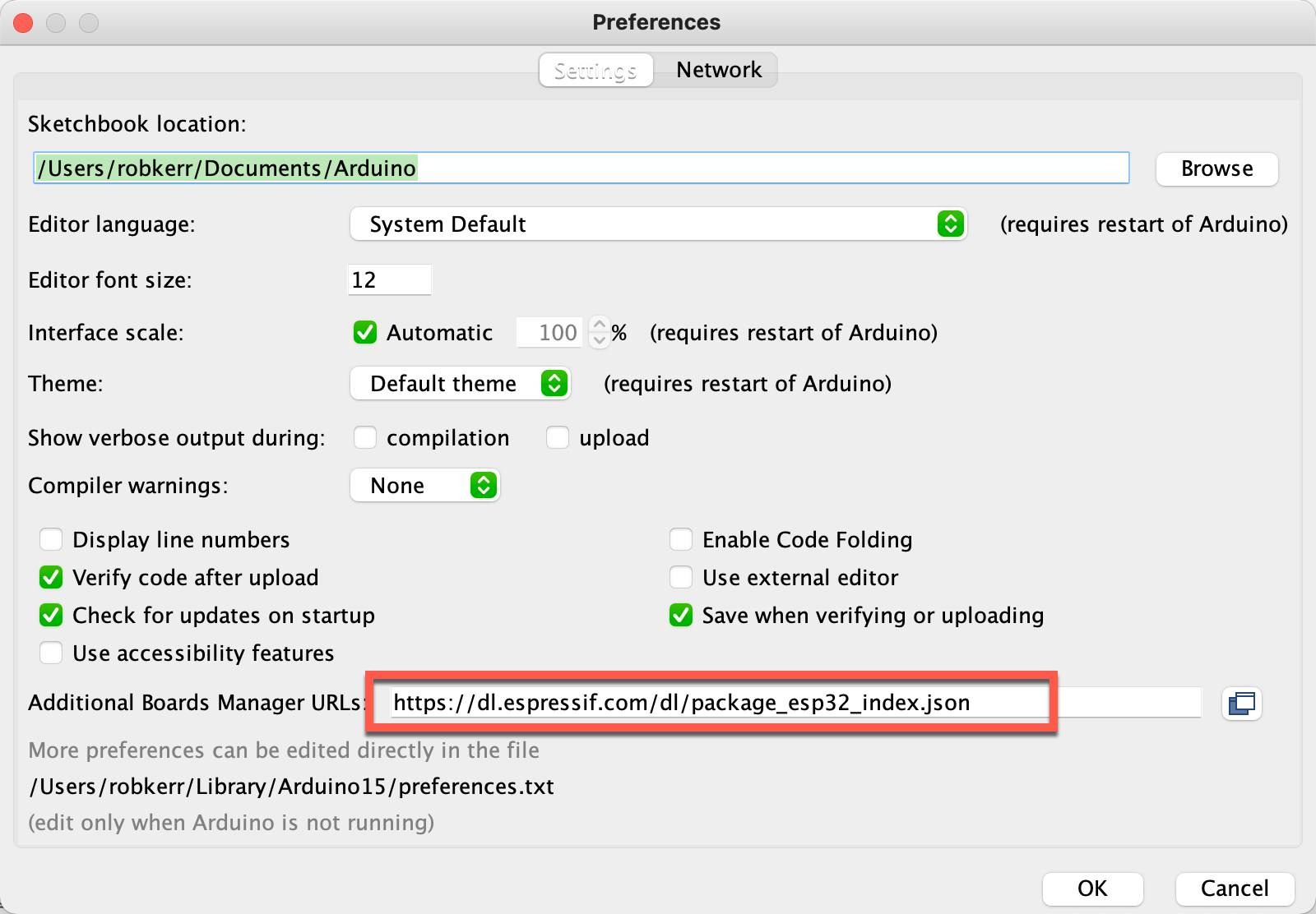
Board Software Support Configuration
Within the Preferences dialog, add the following entry in the Additional Boards ManagerURLs:
https://dl.espressif.com/dl/package_esp32_index.json
Once done click OK on the preference screen to save this option.
Board Manager
To install hardware (board) support, open the Boards Manager from the Arduino Tools/Board menu:
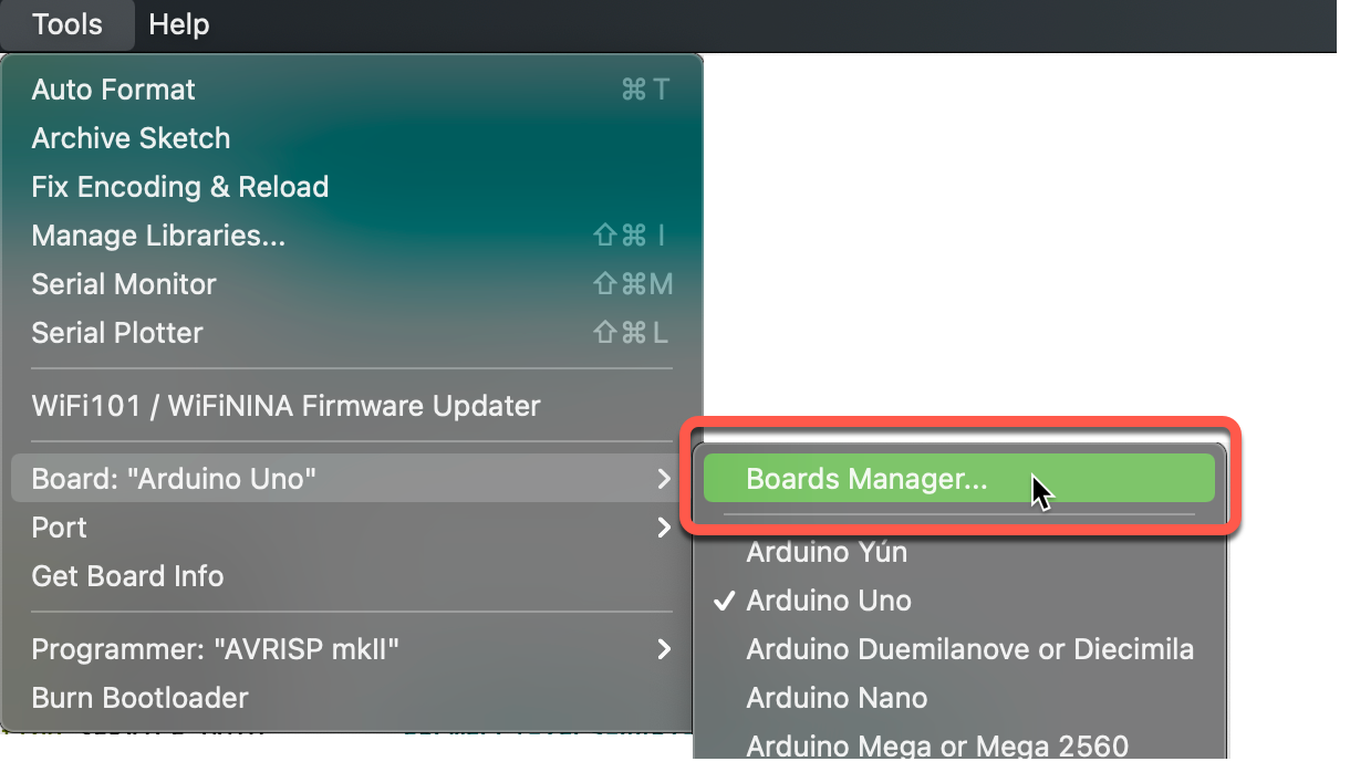
Boards Mananger Menu Selection
When the Boards Manager opens, enter “esp32” in the search bar. Once the list is filtered to the “esp32 by Espressif Systems” item, install the latest version.
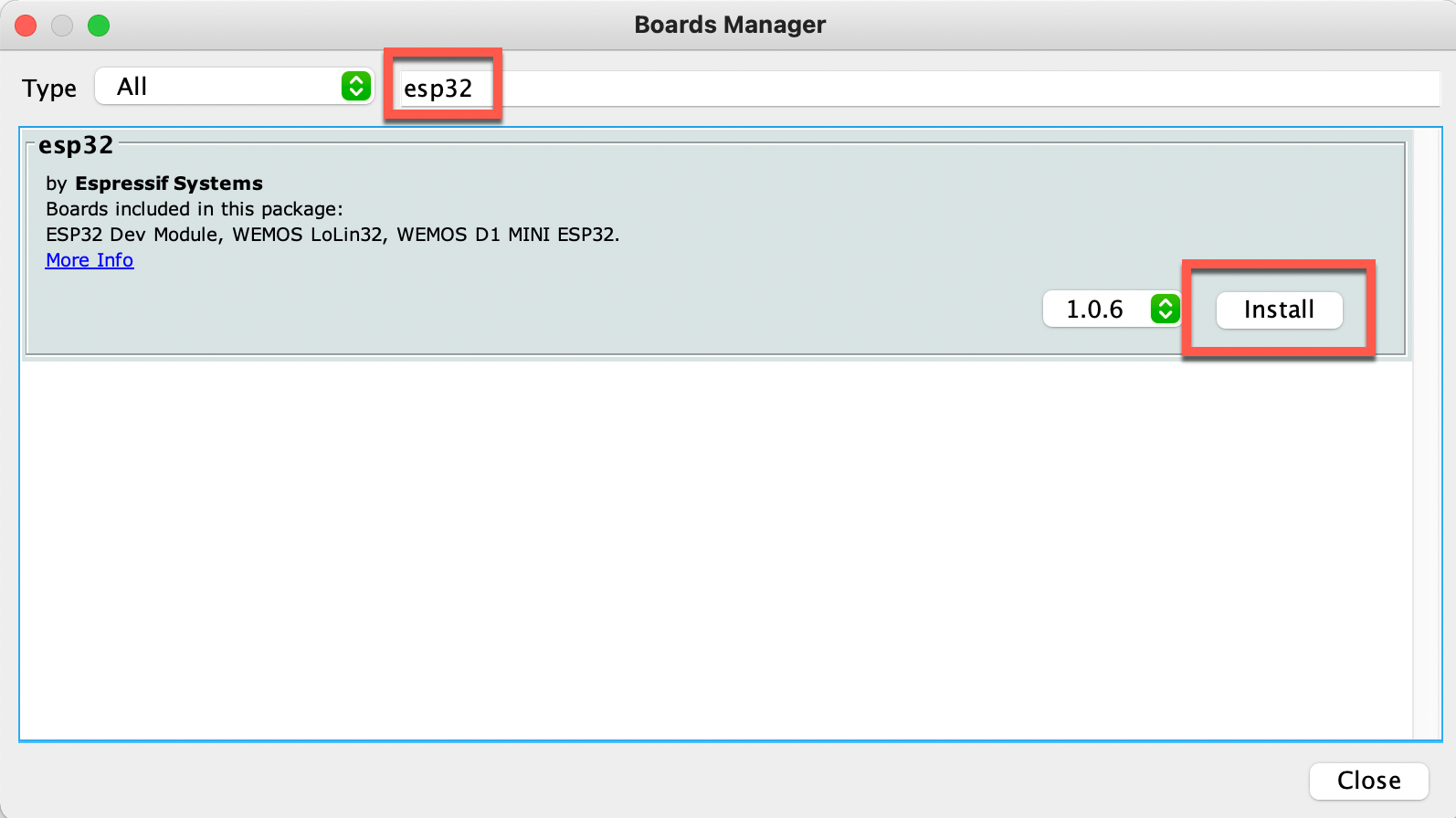
Arduino IDE Boards Manager
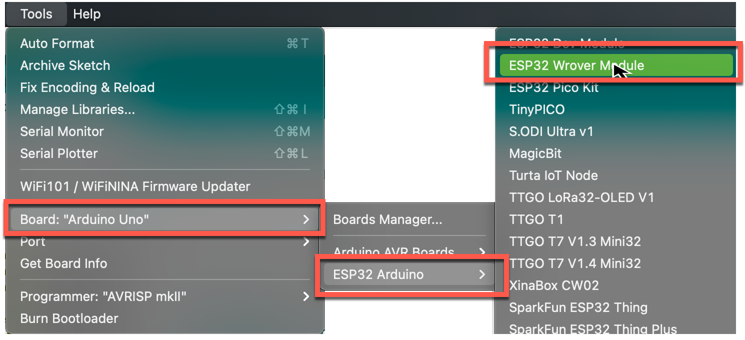
After the ESP32 board support is installed, you’ll notice that a new submenu for the various ESP32 boards will be added to the Tools menu. Select the correct entry for the board you purchased to complete this project.
For the The Teyleten Robot ESP32 board, the ESP32 Wrover Module selection is recommended (but the ESP32 Dev Module should work as well).
Coding the BLE Peripheral
Now that all the hardware and library setup is complete, we can move on to writing some code for the BLE peripheral.
Create a new Sketch
In Arduino, a firmware program is called a “Sketch”, which is fundamentally a text file having an “.ino” file extension. All the code for the BLE peripheral will be self-contained in a single Sketch file.
When you write the firmware code, you’ll be using C++ to implement the firmware.
To get started, select File/New within the Arduino IDE:
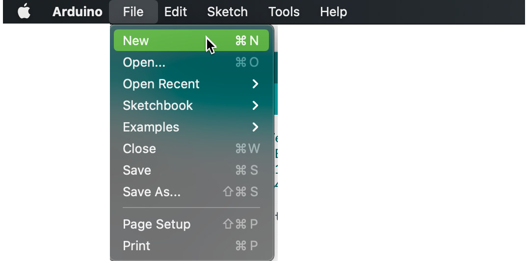
Create a new Arduino Sketch
The IDE will create a new file with two stubbed functions, as below:
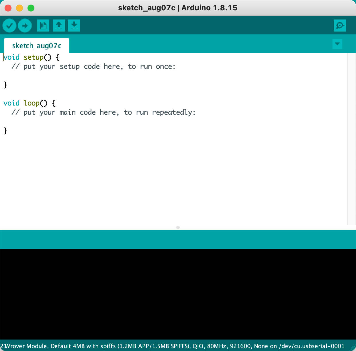
A Sketch Boilerplate Program
Every Arduino sketch program has this basic structure:
- A
setup()function is called when the ESP32 module is powered up or reboots. Typically this is where data structures and daemon services used during the device power on lifecycle are defined. - A
loop()function is the run loop for the firmware, and anything included in this function is run repeatedly and forever. Many firmware application require no extra code in theloop()function.
BLE Service Components
A simple BLE Peripheral has four primary components:
- A Server that connects the various services and characteristics with the outside world. Think of this as the “main process” of the BLE peripheral.
- One or more Service objects, which are “owned” by the Server object. A service typically collects together related firmware functions. A Bluetooth camera may have one service that accepts commands and reports status to connected clients, a second service that is used to provide images, and a third service to support over-the-air (OTA) firmware upgrade.
- Each Service will contain one or more Characteristics . If a Service is analogous to a web server URL, then a characteristic is analogous to a single GET or POST endpoint beneath the URL. A web server endpoint may support both GET and POST verbs; similarly a characteristic can support both read and write operations.
- Advertising. The BLE peripheral needs to advertise at least one of its services in order to be easily discovered by BLE clients (i.e. mobile apps).
Next we’ll implement the BLE Server, Service and Characteristics. I’ll go through these in detail one-by-one, but if you find it helpful to have the entire source file open, here’s a link to it in my GitHub repo:
Basic BLE Peripheral Implementation Code
Header Files
At the top of the source file, we need to include C ++ header files for the BLE APIs that we’ll be using.
#include <BLEDevice.h>
#include <BLEUtils.h>
#include <BLEServer.h>
Implement the Server
Think of the Server as the BLE process (like an Apache server running on a physical Linux box). It will advertise the included services and characteristics to the outside world, and listen for BLE clients and connect to them.
The Server has a name known to the outside world, which is defined at the top of the source file in global scope:
#define PERIPHERAL_NAME "Test Peripheral"
This #define is used when the service is then created at the beginning of the setup() function:
  BLEDevice::init(PERIPHERAL_NAME);
  BLEServer *pServer = BLEDevice::createServer();
In this code, the device name advertised to clients browsing for the BLE Peripheral will be Test Peripheral.
Next we’ll create services and characteristics, and embed them in this server object.
Implement the Service
The calculator app is a simple BLE Peripheral, and only has one service, which accepts two UInt8 operands and a UInt8 operator from a client app. The data is transmitted to the Peripheral via BLE via a write-enabled characteristic. The service then adds, subtracts or multiplies the operands. It returns the result via a read characteristic.
Each service exposed by a BLE Peripheral is identified by a unique UUID. The Calculator’s one service has this UUID:
#define SERVICE_UUID "EBC0FCC1-2FC3-44B7-94A8-A08D0A0A5079"
BLE defines some standard UUIDs for consistency (e.g. “Blood Pressure Measurement Service”). Custom services typically use custom UUIDs. To generate UUIDs using the terminal in macOS, you can use the uuidgen utility, or one of the many public web sites available for this purpose:
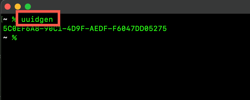
Generating a UUID on macOS
With the service UUID #define in place, we can now create a service identified by the UUID, and add it to the Server object created in the last section.
BLEService *pService = pServer->createService(SERVICE_UUID);
Now with the Service created, we’ll create the read and write characteristics.
Implement The Write Characteristic
Characteristics are the functional endpoints client apps will use to exchange data with the BLE service—similar to a RESTful API endpoint. Like BLE services, BLE Characteristics are identified by UUIDs.
In this application, the single write characteristic is used by the application to send two operands and a mathematical operator to use in a simple calculation as a byte array.
For example, if the application wants the Peripheral to add 2 and 3, it would write the following payload, where 2 and 3 are the operands, and 0 indicates addition.
\[0x02, 0x03, 0x00\]
In the firmware as implemented, the third byte supports three operators:
0 = add, 1 = subtract, and 2 = multiply.
It’s a very simple calculator!
The following code creates the write characteristic that accepts data from the client device, and adds it to the Service created in the previous section:
BLECharacteristic *pInputChar
      = pService->createCharacteristic(
                    CHARACTERISTIC_INPUT_UUID,
                    BLECharacteristic::PROPERTY_WRITE_NR |
                    BLECharacteristic::PROPERTY_WRITE);
This code is similar to creating the service. The additional properties indicate that this characteristic is a write characteristic (i.e. the connected client can write to it), and that clients may write with or without response.
- “With response” (
PROPERTY\_WRITE) is a way for a client to await acknowledgement that a write was successful - “No Response” (
PROPERTY\_WRITE\_NR) means a client will send data to the Peripheral and will not wait for a response. By specifying both with a bitwise OR operator, we’re telling the BLE stack that a client may use either technique (whichever it chooses to use).
Responding to Input Data
In the last section we created a characteristic the client app can use to send operands and operators, but we need to parse that data, process it, and respond with the mathematical answer. Let’s do that next.
Above the setup() function, define a C++ object that implements the BLECharacteristicCallbacks interface, and contains a method that will be called when the remote app writes data to the write characteristic:
class InputReceivedCallbacks:
                public BLECharacteristicCallbacks {

    void onWrite(BLECharacteristic *pCharWriteState) {

        uint8_t *inputValues = pCharWriteState->getData();

        switch(inputValues[2]) {
          case 0x00: // add
            outputData[0] = inputValues[0] + inputValues[1];
            break;
          case 0x01: // subtract
            outputData[0] = inputValues[0] - inputValues[1];
            break;
          default: // multiply
            outputData[0] = inputValues[0] * inputValues[1];
        }

        pOutputChar->setValue((uint8_t *)outputData, 1);
        pOutputChar->notify();

    }
};
Once fully configured, the BLE service will call the onWrite function whenever new data is received. The data is received as a byte array, and the calculator uses the 3rd byte to decide which operator is wanted, then applies the that operator to the operands in the first two bytes.
The result of the calculation determines the new value for the read characteristic (described in more detail below). If the client app subscribed to the read characteristic, a notification message is sent via BLE to let the app know the value has changed (this avoids polling characteristics, saving precious bandwidth and battery life).
To use this callback object, return to the setup() function, create an instance of InputReceivedCallbacks, and add it to the write characteristic’s configuration. The BLE Service will call the onWrite function whenever the remote app sends new data.
pInputChar->setCallbacks(new InputReceivedCallbacks());
The Read Characteristic
In this application, the read characteristic holds the result of calculations. Since there’s no data processing, this characteristic is simply defined and a handle to it retained in a variable.
pOutputChar = pService->createCharacteristic(
                        CHARACTERISTIC_OUTPUT_UUID,
                        BLECharacteristic::PROPERTY_READ |
                        BLECharacteristic::PROPERTY_NOTIFY);
This code creates a characteristic object, and:
- provides the UUID
- Defines the characteristic as a read characteristic
- Allows a client to subscribe to updates
Starting the BLE Peripheral Service
Now that all the components of the service are configured, the service is started via this single line of code:
pService->start();
This BLE service will be running in on one of the two CPU cores in the background. There could be other services running as well (e.g. WiFi, device control, MQTT, etc.). Like a web server, a BLE Peripheral can run multiple services simultaneously.
Advertising the Service
So far the BLE Service is running, but there’s one more step we need for client applications to be able to use the calculator — advertising.
If you’ve ever connected to a pair of headphones or a Bluetooth keyboard, you’ve selected the peripheral from a list. Peripherals get into those selection lists by advertising. They can advertise all of their services, or just some of them. But if they don’t advertise any services, they won’t be readily discoverable from the outside world.
The advertising for the calculator service is defined as follows, at the bottom of the setup() function:
1: BLEAdvertising *pAdvertising = BLEDevice::getAdvertising();
2: pAdvertising->addServiceUUID(SERVICE_UUID);
3: pAdvertising->setScanResponse(true);
4: BLEDevice::startAdvertising();
- Line 2 adds the Service’s UUID to the list of services the Peripheral should advertise
- Line 3 enables response to client scanners that request detailed data about the BLE Peripheral
- Line 4 starts the BLE Device’s advertising service
At this point the peripheral is code complete and ready for deployment to the firmware.
Compiling the firmware source code
Compile the Sketch source using the Arduino IDE to verify there aren’t any syntax (compile-time) errors. Do this by tapping the check mark icon at the top-left of the Sketch editing window.
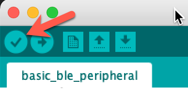
Compiling an Arduino Sketch
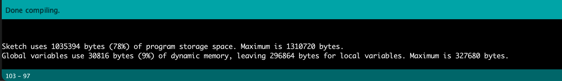
If the compile succeeds, you’ll see some memory statistics for the build in the bottom pane of the IDE (and no errors!).
Connecting to the ESP32 via USB
You’ll flash firmware to the ESP32 via a USB cable connected between your computer and the USB port on the ESP32. The ESP32 will also use this cable connection for DC power.
The USB port is configured on your workstation as an RS-232 Serial port. The following link can be helpful in identifying which serial port an ESP32 is connected to (and driver links are there for Windows users if needed):
Espressif serial connection troubleshooting
For macOS, I find that using the following command from terminal can quickly identify the serial port ID of the ESP32 device:
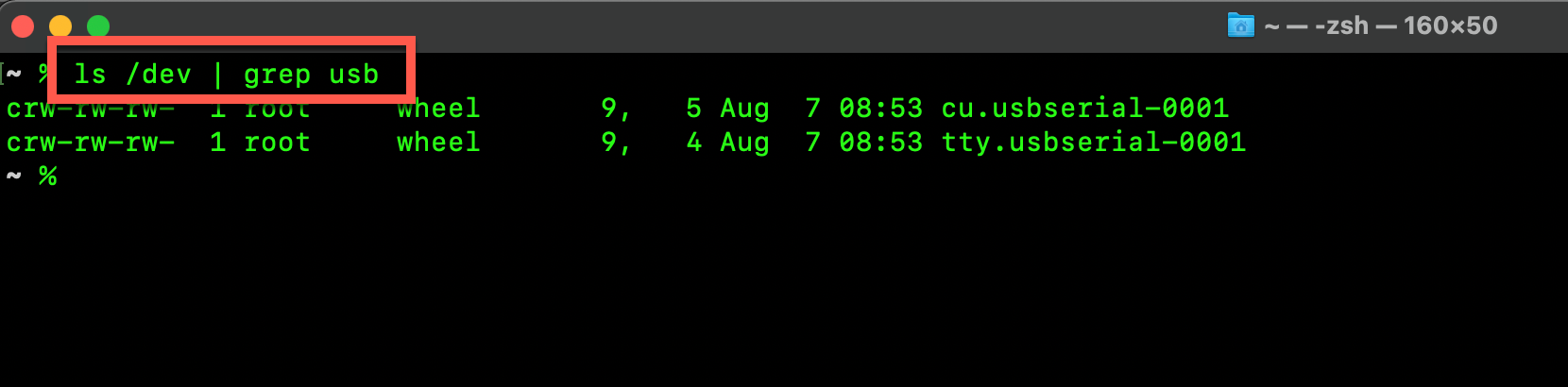
Checking the USB for the ESP32 Module
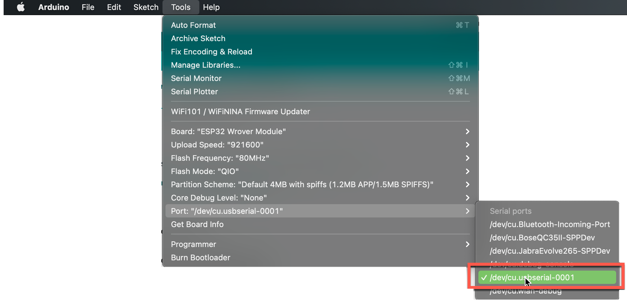
Once the serial port ID for the ESP32 device is known, select it from the Tools menu in the Arduino IDE. This is the port Arduino IDE will use to upload firmware and display console output from the firmware program.
Flashing the Firmware
Flashing the firmware is done by tapping the right-arrow icon in the Sketch window toolbar. This process is basically the same as the compile step, except that after compiling, the finished binary is transferred to the ESP32 via the USB cable.
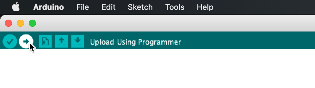
Uploading compiled firmware to the ESP32
As the firmware is uploaded to the ESP32, you should see output similar to the below (some detail removed for brevity):
    Sketch uses 1035394 bytes (78%) of program storage space. Maximum is 1310720 bytes.
    Global variables use 30816 bytes (9%) of dynamic memory, leaving 296864 bytes for local variables. Maximum is 327680 bytes.
    esptool.py v3.0-dev
    Serial port /dev/cu.usbserial-0001
    Connecting........_
    Chip is ESP32-D0WDQ6 (revision 1)
    Features: WiFi, BT, Dual Core, 240MHz, VRef calibration in efuse, Coding Scheme None
    Crystal is 40MHz
    Uploading stub...
    Running stub...
    Stub running...
    .
    .
    Compressed 1035504 bytes to 584710...
    Writing at 0x00010000... (2 %)
    Writing at 0x00014000... (5 %)
    Writing at 0x00018000... (8 %)
    .
    .
    Writing at 0x00098000... (97 %)
    Writing at 0x0009c000... (100 %)
    Wrote 1035504 bytes (584710 compressed) at 0x00010000 in 9.4 seconds (effective 877.6 kbit/s)...
    Hash of data verified.
    Compressed 3072 bytes to 128...
    Writing at 0x00008000... (100 %)
    Wrote 3072 bytes (128 compressed) at 0x00008000 in 0.0 seconds (effective 1038.2 kbit/s)...
    Hash of data verified.

    Leaving...
    Hard resetting via RTS pin...
Arduino Compiler Output
After “hard resetting”, your firmware is running on the ESP32—hooray!!
If the firmware upload its tuck on the “Connecting…..” Step, try holding down the “BOOT” button on the ESP32 module—typically it can be found on the PCB next to the USB port.
Verifying the Firmware is Working
In part two of this series, I’ll walk through developing an iOS application to use the BLE calculator service. In the meantime, let’s do a quick test of whether the firmware is running and advertising correctly.
Monitor the serial output
In the final GitHub peripheral code, there are output commands as the firmware starts up and communicates with a client device. Start the Arduino Serial Monitor by pressing the icon on the top-right of the Sketch editing window to view that output.
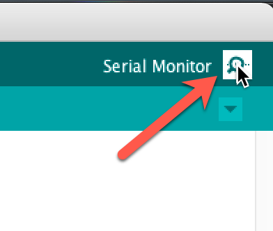
Opening Serial Monitor
Now power cycle the ESP32 (unplug and reconnect the USB cable). If all is well, you should see the following output as the last lines in the serial monitor. These are printed to the console as the first and last lines of the setup() function.
Begin Setup BLE Service and Characteristics
BLE Service is advertising
Serial Monitor Output
Check with LightBlue
LightBlue and nRF Connect are free apps available for Android, iOS and Apple Silicon Macs (possibly others) that can be used to check whether BLE services are advertising and operating as expected.
Using LightBlue, we can verify that the Test Peripheral is advertising, and then by connecting to it, we can see that the service and two characteristics are available to connected clients.
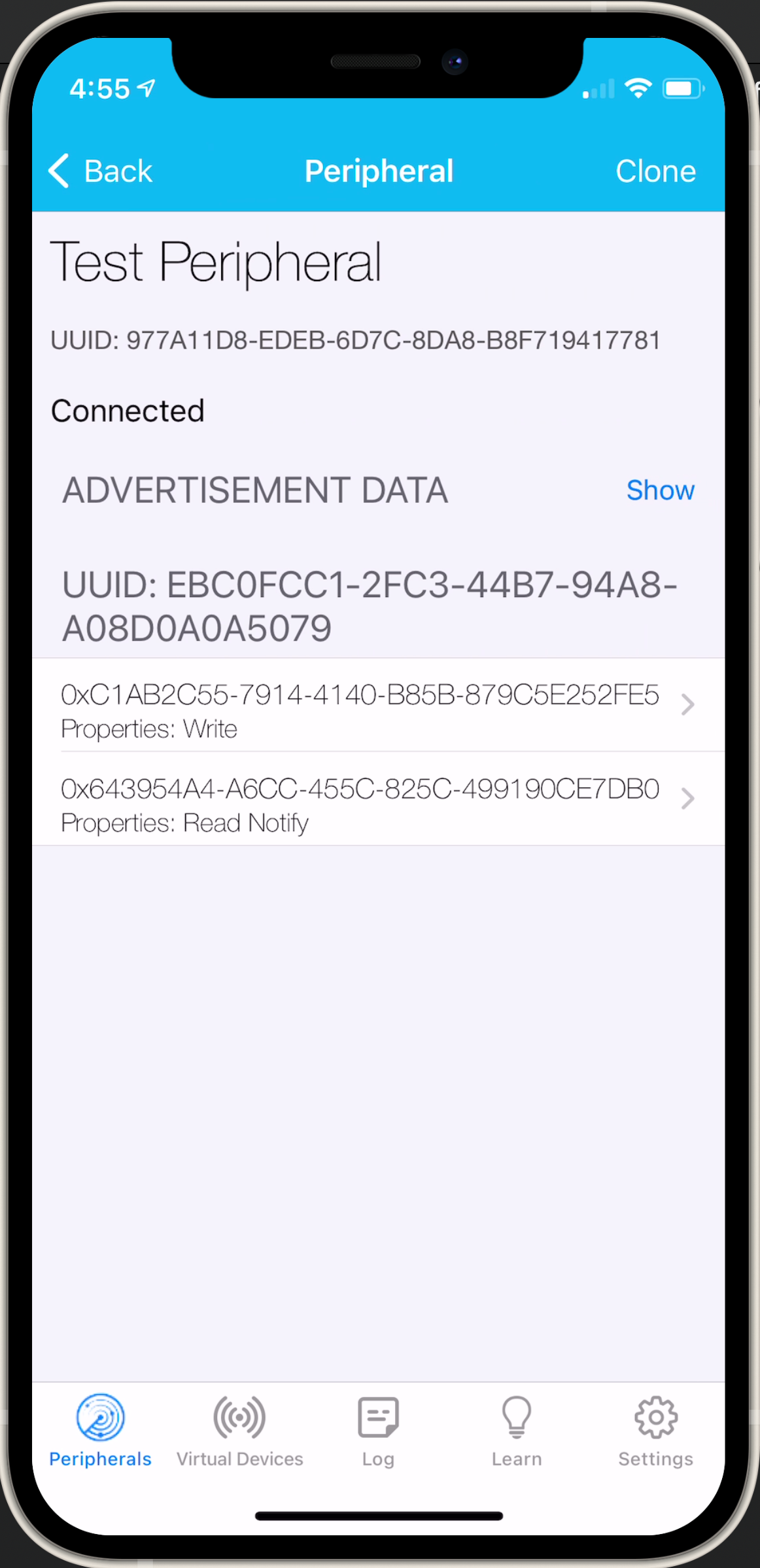
LightBlue inspecting ther ESP32 Firmware Configuration;
It’s also possible to interact with the characteristics using these utility apps, but we’ll leave that level of testing for the next post in this series. If you see the same characteristics as above, the firmware is working correctly.
Completed Code
Here’s a GitHub link for the completed source code.
Summary
In this tutorial post we created a new BLE Peripheral using an Espressif ESP32 platform. The entire BLE service including calculator functionality was less than 100 lines of code!
There’s much, much more than can be done with these cost-effective ESP32 modules, but with a little effort and a gentle learning curve, they can be very helpful to app developers seeking to more fully understand the BLE protocol or need to build a simulator for a device they may not have physical access to.
In the next section of this tutorial, we’ll build an iOS application using SwiftUI to connect to this BLE peripheral and use it as part of the front-end calculator application.
Next: Create an iOS Application to connect to the ESP32 Firmware